Elementary theory of Notches and Weirs:
A notch is an opening in the side of a measuring tank or reservoir extending above the free surface. A weir is a notch on a large scale, used, for example, to measure the flow of a river, and may be sharp edged or have a substantial breadth in the direction of flow.
The method of determining the theoretical flow through a notch is the same as that adopted for a large orifice.

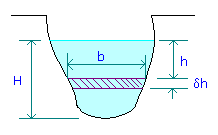
For a notch of any shape shown in figure, consider a horizontal strip of width b at a depth h below the free surface and height dh.
Area of strip = bdh.
Velocity through strip = Ö (2gh)
Discharge through strip, dQ = Area x velocity = bdhÖ (2gh).
Integrating from h = 0 at the free surface to h = H at the bottom of the notch,
Total theoretical discharge(Q),
![]() à 1
à 1
Before the integration of equn.1 can be carried out, b must be expressed in terms of h.
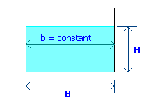
For a rectangular notch, put b = constant = B in equn.1 giving,
 à 2
à 2
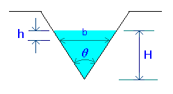
For a V-notch with an included angle q, put b = 2(H-h)tan(q/2) in equn.1, giving

i.e.,
 à 3
à 3
Inspection of equns.2 and 3 suggests that, by choosing a suitable shape for the sides of the notch, any desired relationship between Q and H could be achieved.
As in the case of orifice, the actual discharge through a notch or weir can be found by multiplying the theoretical discharge by a coefficient of discharge to allow for energy losses and the contraction of the cross-section of the stream at the bottom and sides.
In the forgoing theory, it has been assumed that the velocity of the liquid approaching the notch is very small so that its kinetic energy can be neglected; it can also be assumed that the velocity through any horizontal element across the notch will depend only on its depth below the free surface. This is a satisfactory assumption for flow over a notch or weir in the side of a large reservoir, but, is the notch or weir is placed at the end of a narrow channel, the velocity of approach to the weir will be substantial and the head h producing flow will be increased by the kinetic energy of the approaching liquid to a value
x = h + v12/(2g),
where v1 is the mean velocity of the liquid in the approach channel. Note that the value of v1 is obtained by dividing the discharge by the full cross sectional area of the channel itself, not that of the notch. As a result, the discharge through the strip will be
d
Q = bdhÖ (2gx).Coefficient of Discharge for Rectangular Weir:
Coefficient of discharge for rectangular weir given by Rehbock is,

Where P is the height of weir crest in meter.
H is the head over crest in meter.
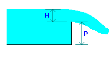
The above equation is valid for P from 0.1 to 1.0 m and H from 0.024 to 0.6 m.
When the length of crest of the weir is same as the width of the channel, the weir is said to be suppressed weir. Thus in this case, the effects of sides of the weir is eliminated or suppressed. Thus for suppressed weirs, length of weir crest = width of channel.
Contracted weirs:
When the crest length of a rectangular weir is less than the width of the channel, there will be lateral contraction.
Flow rate (Q) for contracted rectangular weirs is estimated from,

Where n is the number of contractions.
n = 0 if the notch is full width of the channel;
n = 1 if the notch is narrower than the channel but is arranged with one edge coincident with the edge of the channel;
n = 2 if the notch is narrower than the channel and is situated symmetrically.
When the water on the downstream side of a weir rises above the level of the crest, the weir is said to be a submerged weir.
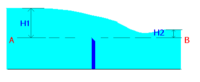
The flow over the submerged weir may be considered by dividing the flow into two portions:
Q1 = (2/3)Cd1B(H1-H2)3/2Ö (2g)
Q2 = Cd2BH2Ö (2g(H1-H2))
Total flow rate Q = Q1 + Q2
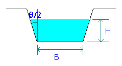
The equation for flow through trapezoidal notch is obtained from the equations for rectangular and V-notches.

Last Modified on: 14-Sep-2014
Chemical Engineering Learning Resources - msubbu
e-mail: msubbu.in[AT]gmail.com
Web: http://www.msubbu.in